Cable Management 3D Modeling Tools. Process Flow Diagram Tower DI and Chilled Water.

Consultant Cad Drawings Equipment Cable Tray Layout Services In Whole World Id 3325849112
See Chapter 8 IC Series D6000 Series.

. Hot lines and cold lines shall be kept apart in different groups on a tier. We will make it for you. If you need a non-stock item dont worry.
As part of our ongoing commitment to customer support Legrands cable management ranges and Cablofil wire mesh cable tray are now integrated into the following plant design modeling systems. In the Cable Tray Layout Preferences dialog box on the Routing tab select Automatically create riser at new Elevation. Piping and Instrumentation Diagram PID.
Piping Instrumentation Diagram Tower DI Chilled Water. Process Flow Diagram HVAC. Trays can be produced of strong steel wire for light-duty applications such as instrument signal cabling or network computer cabling or they can be made of steel or aluminum channel for heavy-duty applications such as electrical energy cabling.
If these cables above would completely fill a 30-inch wide cable tray selecting a 36-inch wide tray in your design would make space available for future cables. These guidelines and information do not intend to cover all details or variations in cable tray systems nor provide for every possible installation contingency. Compatible with AutoCAD and Gstar-CAD.
Acceptance testing cable cable installation cable selection communication cable. Cable tray systems design shall comply with NEC Article 392 NEMA VE 1 and NEMA FG 1 and follow safe work practices as described in NFPA 70E. Channel cable tray ladder cable tray single-rail cable tray wire mesh cable tray solid bottom or nonventillated cable tray and trough or ventilated cable tray and associated fittings for use in accordance with the rules of the National Electrical Code.
Vendor Drawings for PSV Control Valves Flow Meters Level Instruments Pressure Instruments Temperature Instruments etc. Instrument Layout and recommended cable tray routing drawing within battery limit Instrument installation drawing. The final branch cable tray route shall be decided by subcontractor Field Engineer in accordance with the site condition.
PDF CAD Title Date. Click in the Add Cable Trays dialog box. For Construction Engineers with Electro-Mechanical Design Requirements.
Cable tray laying to take care of necessary clearances for the fire proofing of structure. Drawing Number Sheet Rev. Material take-off for instrument cables cable trays tray supports etc.
Every instrument in a loop drawing has an input calibration and an output calibration specified for the instrument. List of alarm points with settings and ranges. Process data sheets for Equipments.
Generally the top tier is to be kept for Electrical cable trays if not provided in underground trench and Instrument cable ductstrays. In the Conduit Layout Preferences worksheet select Automatically create. The data files available are specifically for use with the relevant systems and as such cannot be used or converted.
Material take-off for field instrument installation hardware. The design installation and protection of wire and cable systems in substations are covered in this guide with the objective of minimizing cable failures and their consequences. The formula for calculating the proper cable tray design load for the 36wide cable tray.
All installation requirements and tolerances shall be in accordance with the technical specification the latest construction drawings and the applicable documents shall be SAES-J. We can supply you with the right sizes types and quantities of product you need to keep you on schedule and your management happy. For example in our loop drawing below PDT Pressure Differential Transmitter-42 has an input calibration of 0 -200 PSID and gives out a 4 20mA as output.
Loop drawings specifies the action of an instrument. They are made with the guidelines of Instrument Location Layout and thus helps in grouping junction boxes. Paneldes Raceway software is for construction engineers with electro-mechanical design and cable management requirements such as those designing plant cable raceway ductbank cable tray and cable ladder layout and cable routing.
NEMA VE 1 This standard specifies the manufacturing requirements for metal cable trays such as. Piping Instrumentation Diagram HVAC. This 4 20mA is the output calibration.
Cable trays are open leaving the cables exposed to the environment. Subcontractor shall submit actual cable tray drawing after installation for As-built. We have been doing this for companies since 1947.
Click OK and then enter an elevation in the Add Cable Trays dialog box. Click Preferences on the Properties palette. Wire and cable coaxial cables heat shrinkable products and fi ber optic products.
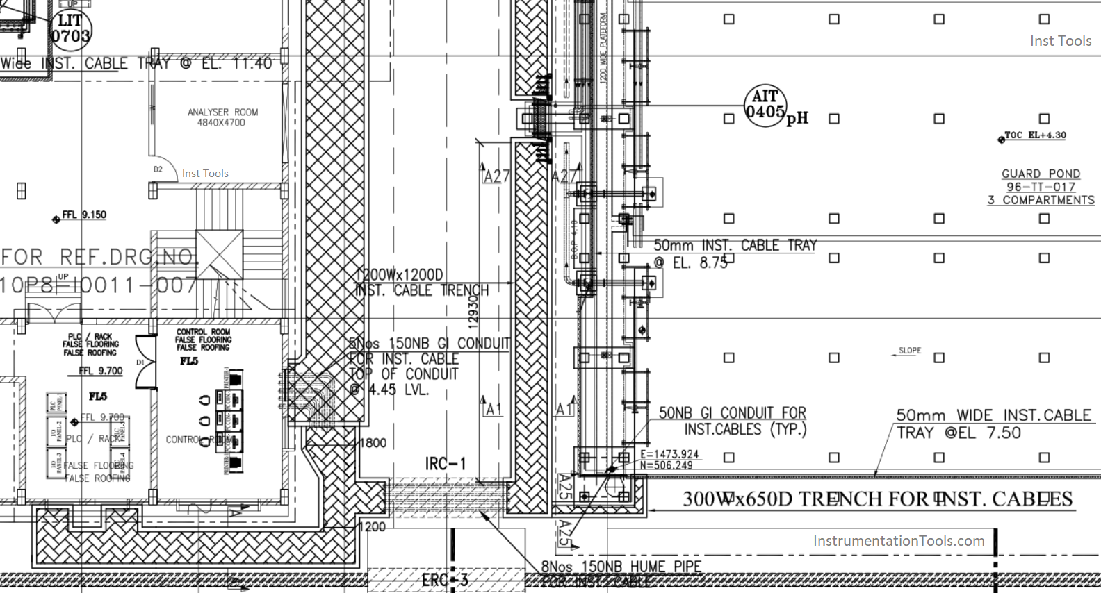
Instrument cable wiring schedule. Instrument Tray Layout is the drawing that shows the location of junction boxes instrument air header local panel the instrument tray routing in the plan view.

List Of Instrumentation Project Engineering Documents

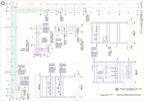
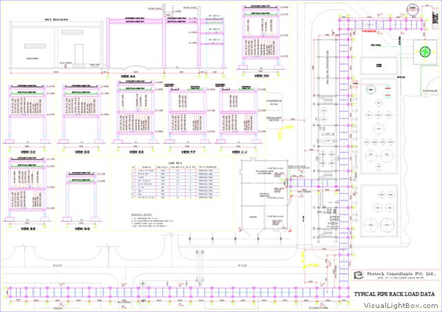
Detail Engineering Protech Consultants Pvt Ltd

Detail Engineering Protech Consultants Pvt Ltd

Typical Design Philosophy Of Cable Trays For Power Plant Cable Tray Cable Trays Cable

Sample Drawings Of Power Distribution Projects Equipment Cable Tray Layout Services Consultants From Kolkata

Sample Drawings Of Power Distribution Projects Equipment Cable Tray Layout Services Consultants From Kolkata

0 komentar
Posting Komentar